|
A collection of notes from various people and sites.
It took me ages to find them since they are so widely scattered - that's why I've assembled them here. If anyone objects, please let me know.
|
General electrical / motor issues.
-
These notes appeared in WACEM and are from Clayton Bonser regarding the Kenwood Chef A901E - I added the highlighting.
- The electronic components all will break down with time and use. The speed control of the governor depends on a resistor and capacitor combination. Replacing them both will smooth out hunting at low speeds. My advice is don't fiddle with the adjustment screws until all other options are exhausted. If you plan to remove the circuit board, measure the gap between the edge of the board and the nearest fixed part so the gap can be reset to close to original. This will save a bit of mucking around later. Make sure the board sits level across the motor by adjusting the screws evenly.
- Any other capacitors are for preventing arcing at the brushes, and/or suppressing RF noise. All capacitors must carry an X2 mark, as well as the capacitance and voltage marks. Lesser ratings indicate that the capacitor is not designed to go between active and neutral, or active and the chassis. Failure of lesser components carries a risk of the housing becoming live should a capacitor fail and 'go short'.
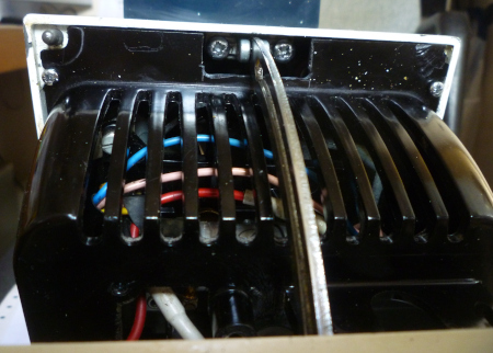
- Whilst you are there, the field winding leads on some Kenwood motors are a problem. (These are the wires that go from the circuit board into the motor housing, usually four of them.) The insulation becomes brittle, and disturbing the wires can lead to shorting (which lets the smoke get out). Removing the field coils and putting new leads in isn't rocket science, but can be daunting. If these wires have crunchy insulation, they will need to be attended to.
- The top bearing in some Kenwood motors can be badly worn, usually in the late model electronic control models. Check this. You should be able to spin the motor shaft freely, but there should be no movement side to side. A worn bearing can be replaced, but they are getting hard to find. Add a wee drop of oil to both bearings when putting the motor back, it'll love you for it.
- The commutator will most likely need to be re-machined. If the copper strips show any evidence of wear or grooving, take the armature to an electric motor repair shop and have it re-machined. Before you do that though, inspect every copper strip. You are looking for evidence of the edges of any strip being burnt and eroded. Should you find such evidence, you can either a. have the armature rewound, or b. find a replacement motor. Burnt strip(s) indicate a short in the windings.
- Replace the red rubber grommets that support the motor. They will be hard, perished and have sagged by now. You can see this because the drive belt will not sit level, but slope down towards the motor pulley.
- Also replace the rubber feet on the machine base. The gap around the base is where the motor cooling air enters, and no feet means an overheating motor. Replacement grommets don't need to be red, but finding ones the right height is a trick. 1/4" washers from a hardware store will pack the motor up to the right height using the commonly available size grommets.
- Once everything is back together in the motor, and the motor is running on the bench, see that there is a smooth transition from lowest to full speed. Many machines I have seen have the speed control set so that for some of the dial there is no speed change. Usually at the high speed end of the dial. This is set using the two adjustment screws that pull the circuit board up and down.
|
More general electrical / motor issues.
-
These notes appeared in WACEM and are from Danny Allcock - I added the highlighting.
- In answer to the question "whilst running the motor on the bench It was intermittently sparking in the contact bar. The motor is vibrating and not running constantly."
- The arcing you have mentioned is due to pitted contacts on the board.
- If the motor hasn't been touched since new, nows the time to give it an overhaul or get someone else to do it.
- There are kits on eBay for the motor @ about £30. And you will need some knowledge of soldering and electronics to keep yourself safe.
- Or for about £100, again on eBay, there is a company who will do all the work needed and give you a 12 month guarantee.
- In answer to the query "when I removed the motor a small fibre like disc with notches in the sides about the size of a penny dropped out broken in 2"
- The little disc that fell out is probably the end of one of the capacitors.
|
High-speed only.
-
- In answer to the query in WACEM about Kenwoods which "only run at high no matter what speed I set it on!- I added the highlighting.
- This answer is from Ran Katz.
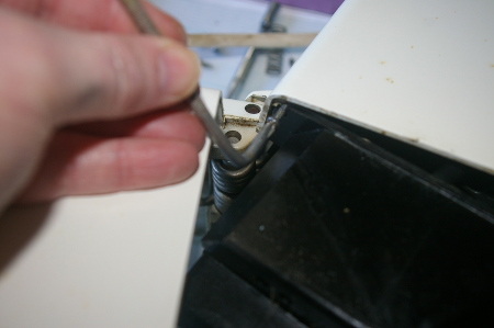
- The "base" (lowest) speed is set by 2 screws that determine the (starting) distance between the control board and the motor/centrifugal governor.
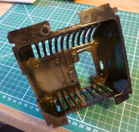
- to get to these screws you need to remove the control/motor body cover - thats the black cover with air vents you see when the mixer is "open".
- For safety reasons please make sure you disconnect the mixer before playing around the control board!
- You should also check that the governor "switch" parts (2 flat springs with round contacts, one on the top and one on the bottom of the control board) are not stuck together for some reason and the governor can operate properly.
- This answer is from Clayton Bonser.
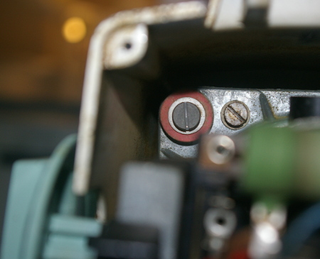
- The speed issue is probably the spark suppression capacitor for the governor. If it "goes short", the motor will run at full speed only. The capacitor, or the original one at least, lives under the Bakelite cover that covers the motor bottom, and looks like a little aluminium can with wires coming out of each end. Replacements usually are little boxes in plastic, but they work the same.
- It is very important that the capacitor is replaced with one of the correct rating. It will have a value, I think about 50 microfarads or so (check, my memory ain't what it used to be). It'll be written on the outside, but the one to pay serious attention to is an X2 mark. This indicates that the capacitor is rated to go across the mains safely.
- It is usual that by the time the capacitor fails, the grease has also aged and is no longer lubricating the gears. In Kenwoods the gears are pressure molded pot metal. They will wear pretty quickly if they don't have good grease.
- You know what to do.
|
Motor mounting grommets.
-
- Note that suitable grommets are available from several of the suppliers listed on my main page.
- These notes are from Anthony Keen - I added the highlighting.
- I am now in the midst of doing an overhaul of my 44 year old Kenwood Chef A701A , declared "unrepairable" by the local agents . The only thing I have found "faulty" so far is that the motor mounting rubbers have totally perished , and slight accidental pressure on the high speed drive shaft caused the whole motor to literally fall out with the four mounting screws still screwed tight ! Motor
works fine (still 11.3 mm of intact carbon brush both sides) and so does gearbox .
Seems like the whole motor was somewhat mobile.
- Am fashioning new rubber mounts from an offcut piece of silicone rubber sheeting (nominal 3 mm thick) . Two discs 20mm diam and one about 16 mm , all with an 8 mm central hole . I "massaged"
the small disc into the large flange hole in motor mount (14.7 mm diam)(I don't have exactly the right sized hole punches , so am making do with existing set of punches).
- With a larger disc above and below the flange the bolt can be pushed through the lot .
Spacing washers are necessary to get the height of the belt drive spindle correct . The
original washers under the bolt head (12.8 mm diam) fit through the motor flange hole
(enabling the motor to fall out when rubbers perished) . Had thought of putting larger
washer here to prevent motor fall out , but this would stiffen up the flexibility of the
mount , so will keep original washers here ( Silicone should not perish in the next 44
years) . I plan a dab of contact adhesive to hold all in place whilst refitting mounting
screws.
|
.
-
-
|
Please let me know if the above helped, or if you found any mistakes (see below).