 If you don't have an Atco Qualcast Trojan 18s lawn mower, then this web page may help with other mower problems.
How to repair an Atco Qualcast Trojan 18s lawn mower |
If you don't have an Atco Qualcast Trojan 18s lawn mower, then this web page may help with other mower problems.
N.B. This web page is only intended to help you work on your mower, but I don't take any responsibility for any damage or injuries which result.
.
Front wheel height adjustment slips. | |
|
This shows my mower, with a high-tech bungee cord clipped on, so as to pull the front height-adjustment levers back towards the body and thus stop them slipping out of the adjustment slots. I found this happened more often when trying to mow near bushes, etc. Presumably this is one reason for later versions of the mower having covers over the levers. N.B. You should realise that, if the cord were to break, fall in front of the mower and thus be hit by the blade, that this would be dangerous. Therefore you should regularly check the cord. |
|
Other work on the front wheels. | |
|
This section shows the various parts of the front wheels, to help with any other problems. This photo shows the wheel and adjuster removed from the body. |
|
|
This shows the wheel assembly, ready to refit on the body. Note that the two sides are interchangeable - only needing the adjuster aligned to the other side. |
|
| This shows the lawnmower body mounting points for the front wheel assembly. |
|
Rear wheel height adjustment slips. | |
|
This shows the my mower, with a high-tech bungee cord clipped on, so as to pull the rear height-adjustment lever back towards the body and thus stop it slipping out of the adjustment holes. If the holes themselves have worn away, see just below here for a fix. |
|
Rear wheel height adjustment failed. | |
|
The adjustment lever on mine failed to stay in place because the holes in the mower body had worn away. What I did was to cut up a piece of angled aluminium to fit over the holes. This I fastened in place with two M8 round-headed bolts. Then I moved the lever back and forth so as to scrape a mark on the aluminium. Then, with the lever moved out of the way, I drilled a new series of holes in approximately the same place as the old. You will need to size these until the pin on the lever just engages each hole. Please note:
|
|
Tube to carburettor loose or cracked. | |
|
This is part number 529 at the top right of the DIY Spare Parts diagram (called a grommet and last seen at only £4.02). I first found that the pipe, leading to the rear of this tube, had become misaligned. A relatively gentle push corrected this. I then found that the tube had split which was corrected with a bit of copper wire taken from an old electrical cable. |
|
Starter flywheel cover loose. | |
|
The cover was mounted, using pop-rivets, on a base which had multiple holes. The holes in the base had become worn. I simply removed base and cover, drilled out the rivets, rotated the cover to the next set of holes and re-fastend it using a new set of pop-rivets. If you don't have a pop-rivet gun, then use suitable bolts, washers and locking nuts (ensuring they don't foul the mechanism it covers. |
|
Exhaust cover broken. | |
|
There are at least two different versions of the exhaust cover. This deals with the sheet metal version. Mine had broken off at a mounting point. My solution was to drill a hole in the remainder, bolt on an extension piece and then use the original bolt to fasten that to the engine. |
|
Repairing the engine mounts. | |
|
This shows one of the mounts on mine, with a rather unfortunate crack developing. You can see that, not unsurprisingly, the engine mount nut is rather the worse for wear. |
|
|
This shows the mower body, stripped of blade and wheels, cleaned off and treated with Hammerite Kurust. You don't need to go quite this far to repair the engine mounts but it's worth sorting out any other problems at the same time. |
|
|
This shows the author, using a subtle technique to remove the old, rusty, engine mounting nuts. You should at least wear safety glasses if doing this. |
|
|
Once the engine is removed, you'll need to cut some strips of aluminium angle to the shape shown here as, basically, large, shaped washers. They will need to:
Please note that this shows them held in place with M8 bolts going up and that I changed this when I realised that, if they ever worked loose, the bolts would fall down onto the blade and cause bad things to happen. I thus refitted them the other way up (see below), using lock nuts and suitable washers. |
|
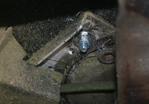
| This shows one of the engine mounts, from above. This being one that is easy to reach. |
|
|
This shows (blurrily - sorry) another engine mount, where it is positioned below the fuel tank. You will need to loosen the carburettor, which is simple, to allow the bolt to be inserted and tightened. |
|
|
This shows the lock nut and washer, for one mounting point, fitted below. Note that a washer, as large as possible, is needed to prevent the aluminium piece from being distorted when tightening the nut. |
|
|
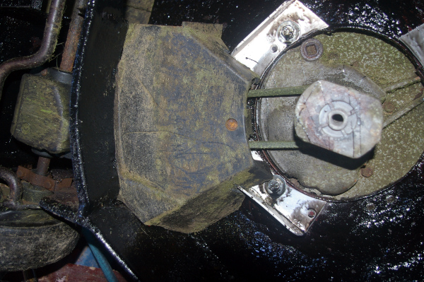
This shows the belt, belt cover and rear axle refitted. Note that I had to cut grooves in the cover to fit over the new pieces. |
|
Please let me know if the above helped, or if you found any mistakes or better solutions (see below).
| Web site main menu |
This page last updated 16th. August 2020.
Images and text © Copyright Jim Batten, 2019-2020.